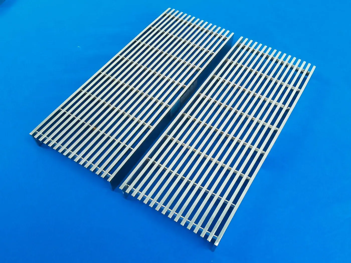
Rectangular bearing bar
A regular grid using rectangular bearing bars; confirm section size, spacing, span and load from the project requirement.

Engineering
Steel Grating Load Tables: How to Read and Use Them Steel Grating Sizes and Dimensions: What Each Number Means Steel Grating Standards Guide: NAAMM, ASTM, ISO and Regional CodesEngineered Around Your Load & Span
Swage-locked grating is mechanically assembled by locking cross bars through the bearing bars. It is commonly specified for lightweight aluminum access systems where panel weight, corrosion behavior and a stable grid matter.
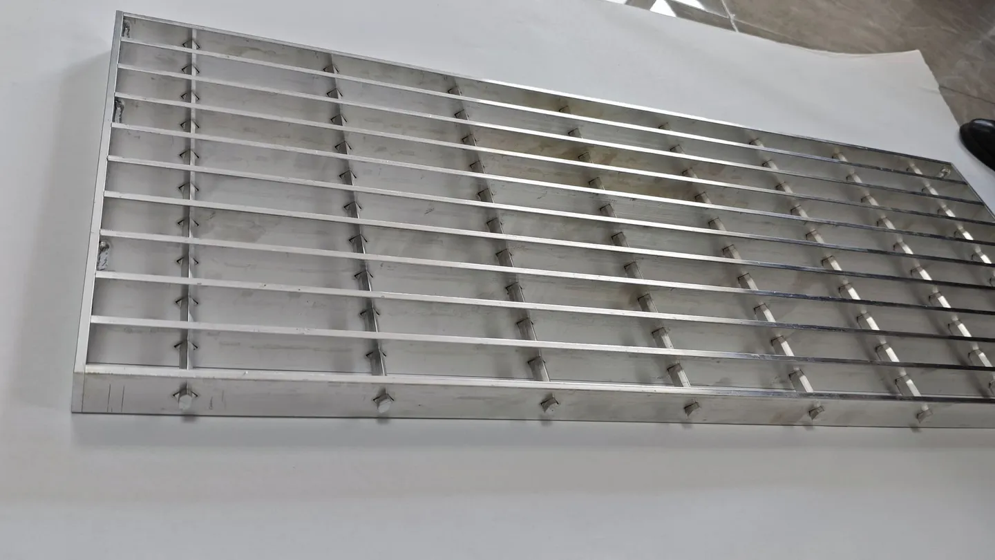
Swage-locked grating is formed by inserting cross bars through pre-punched bearing bars and mechanically deforming the cross bars at each intersection. The deformed locking points stabilize the grid without resistance-welding every intersection.
Series names and bar profiles vary by specification. Similar-looking panels are not automatically interchangeable, especially when replacing an existing access panel.
We confirm the bearing bar profile, cross-bar arrangement, spacing, alloy, span, load and support condition before preparing a panel layout or quotation.
A useful identification photo shows both the top grid and the panel edge: the bearing-bar profile, cross-bar shape and deformed locking points can be difficult to distinguish from a distant top view. For replacement work, these details matter more than a visual match of the opening size alone.
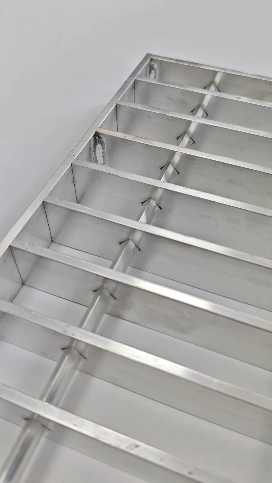
Locking Sequence
The construction is defined by the way each cross bar is inserted and mechanically deformed through the bearing bars. Confirm the sequence for the selected profile and spacing series.
Bearing-bar profile, pre-punched hole pattern and spacing are prepared to the confirmed series or approved drawing.
Cross bars pass through the aligned bearing-bar openings so the grid and bearing direction match the panel layout.
Mechanical deformation locks the cross bars at the intersections before banding, cut-outs and other drawing-led fabrication are completed.
Workshop Evidence
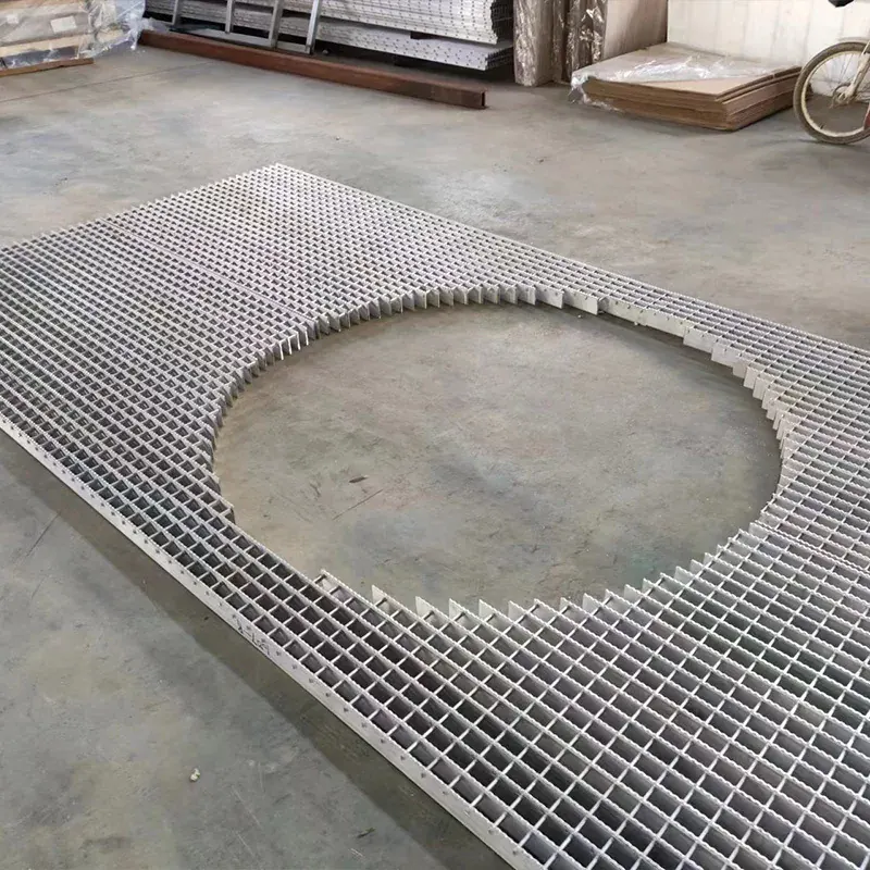
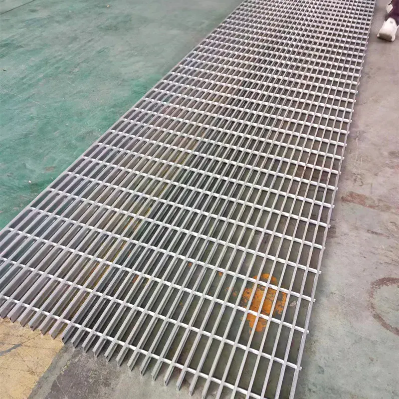
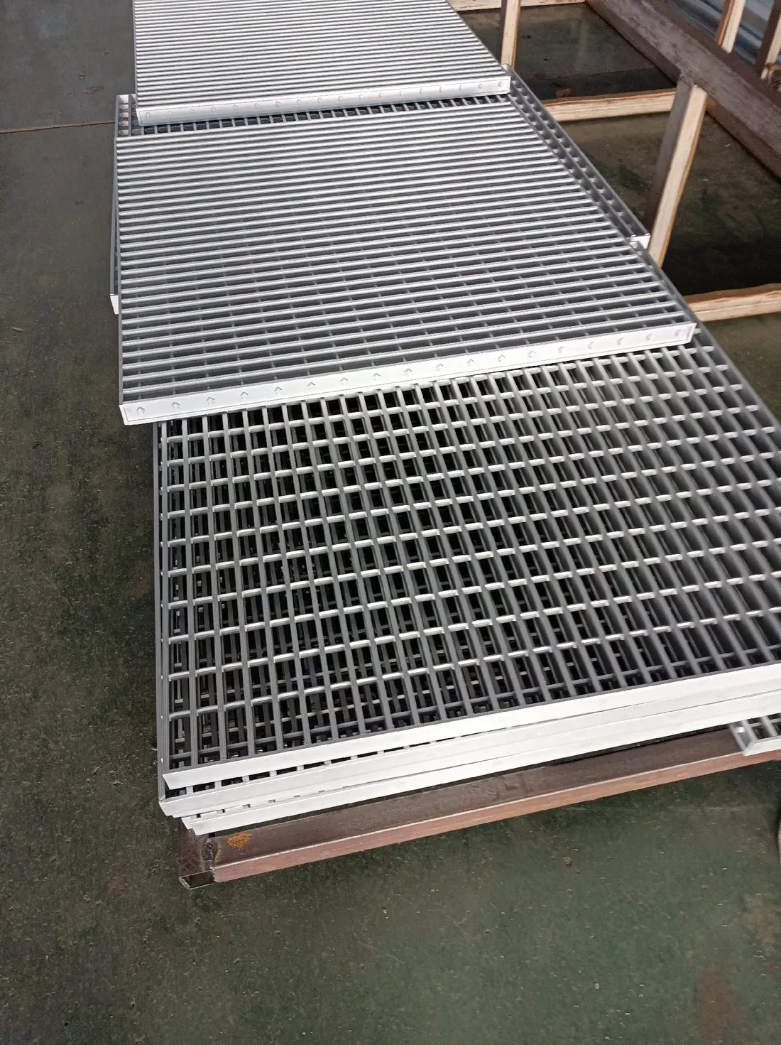
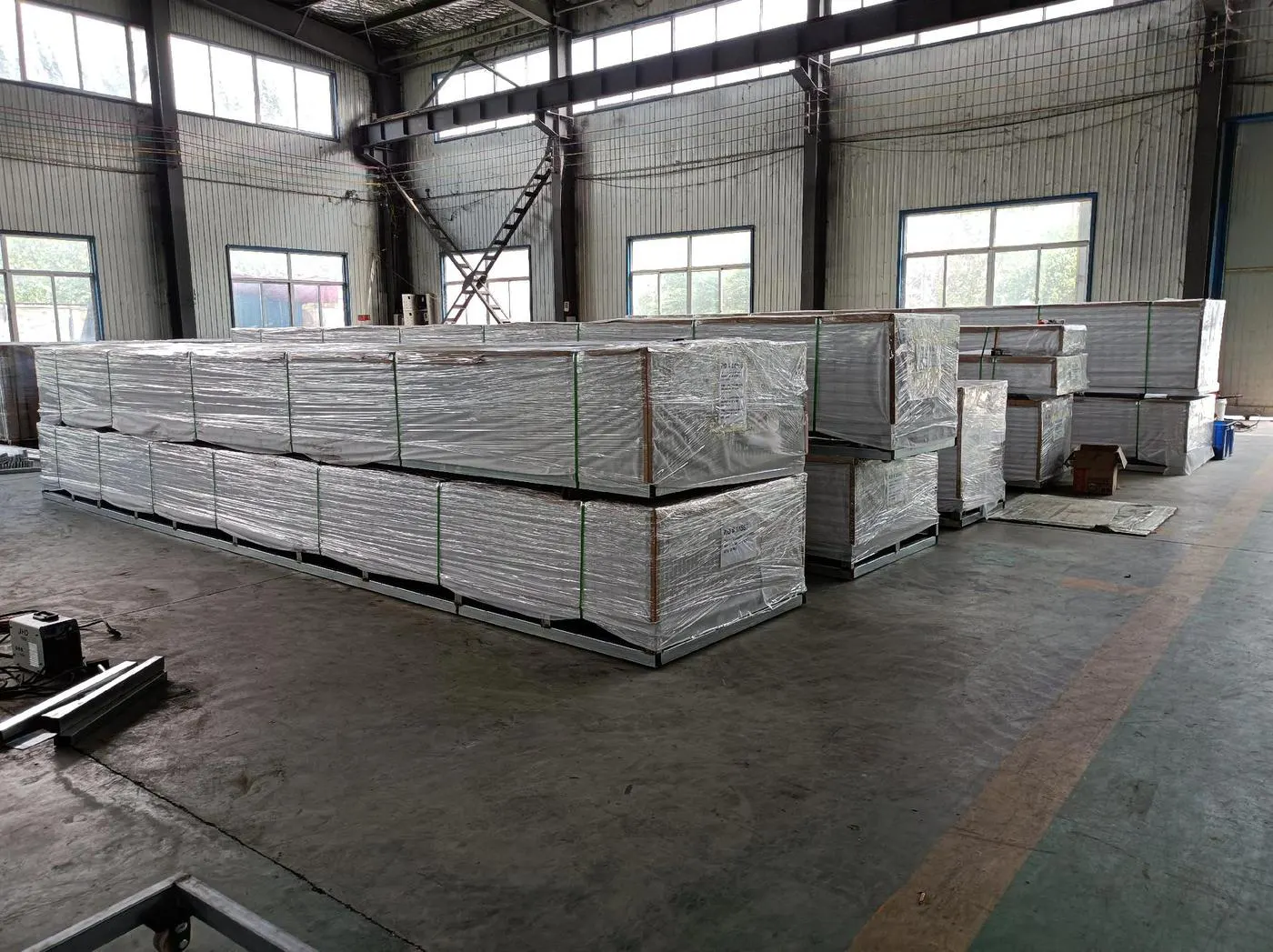
These photographs show non-standard openings, long-format panels and fabricated batches in the workshop. They demonstrate layout and fabrication possibilities; the exact swage-locked series, remaining bar arrangement and load case are confirmed separately for each drawing.
Specifications
| RFQ input | What to send | Why it matters |
|---|---|---|
| Material | Aluminum alloy, temper and required finish from the project specification. | Material condition must be confirmed with the profile, forming route, exposure and finish. |
| Bearing bar profile | Rectangular or I-bar profile, including a section photo for replacement work. | Similar top openings can hide incompatible bearing-bar and locking systems. |
| Bearing bar size | Depth and thickness, or the required load together with the clear span. | The section and span are primary load-selection inputs. |
| Bearing bar spacing | Centre-to-centre spacing or the named project series. | Spacing changes the opening, open area, weight and load distribution. |
| Cross bar | Cross-bar shape, dimensions, spacing and a close photo of the locking point. | These details identify the swage-lock system and replacement compatibility. |
| Walking surface | Plain or serrated surface and any opening-size restriction. | Surface and opening requirements affect grip, passage and available profiles. |
| Span and supports | Clear span, bearing-bar direction, support width and fixing locations. | Panel length alone does not identify the unsupported design span. |
| Load and deflection | Uniform, concentrated or wheel load plus the required deflection limit. | Pedestrian and equipment loads must be checked as separate design cases. |
| Panel layout | Panel dimensions, bearing direction, piece marks, removable areas and support lines. | A layout drawing prevents incorrect panel divisions and bearing direction. |
| Fabrication and order | Banding, cut-outs, quantity, destination, project standard and required documents. | These inputs define the practical fabrication, packing and quotation route. |
Variants
A regular grid using rectangular bearing bars; confirm section size, spacing, span and load from the project requirement.
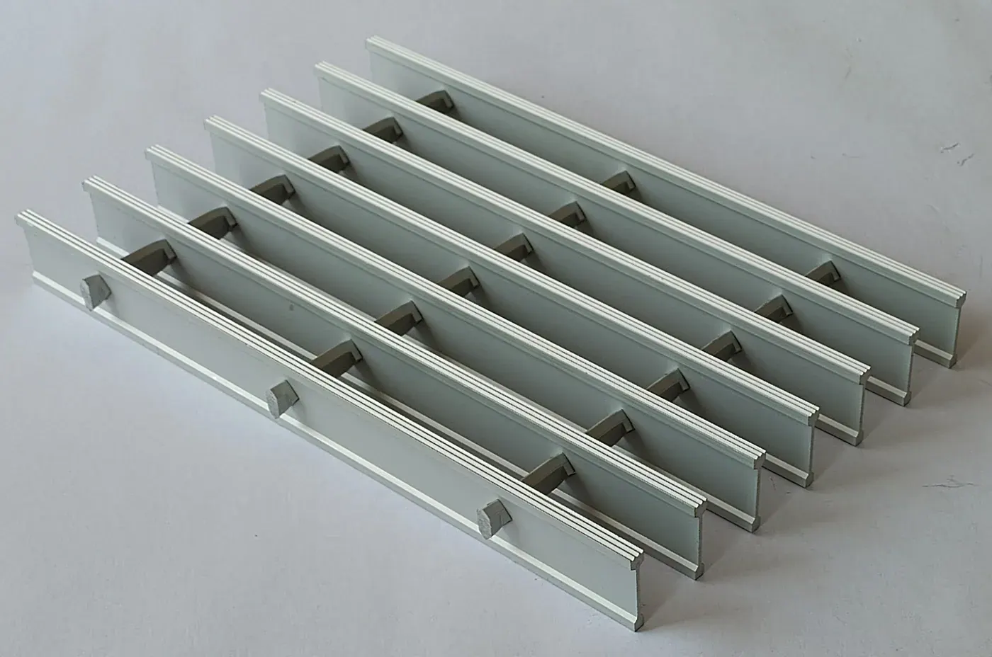
A lightweight profile used only where the selected system and load case permit it.
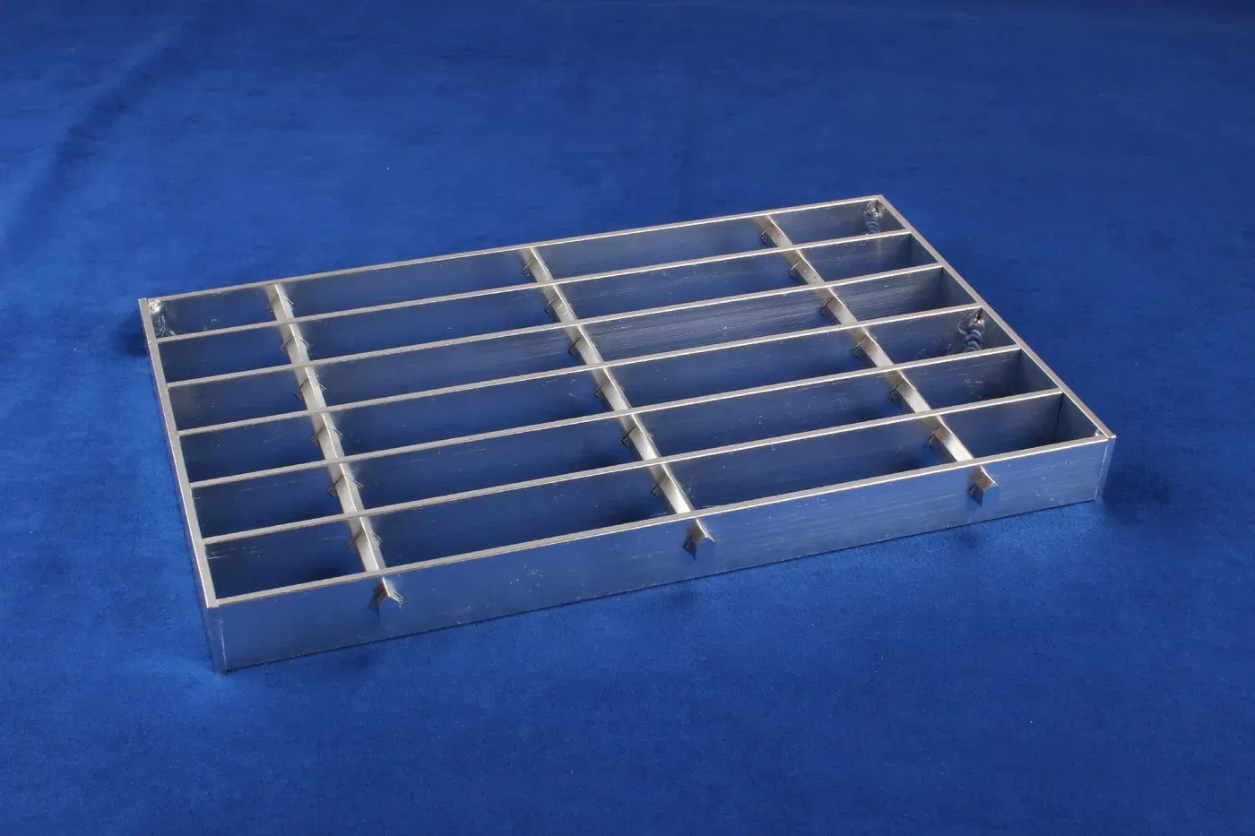
A smooth-top bearing-bar option for projects where the surface, opening and environment do not require serrations.
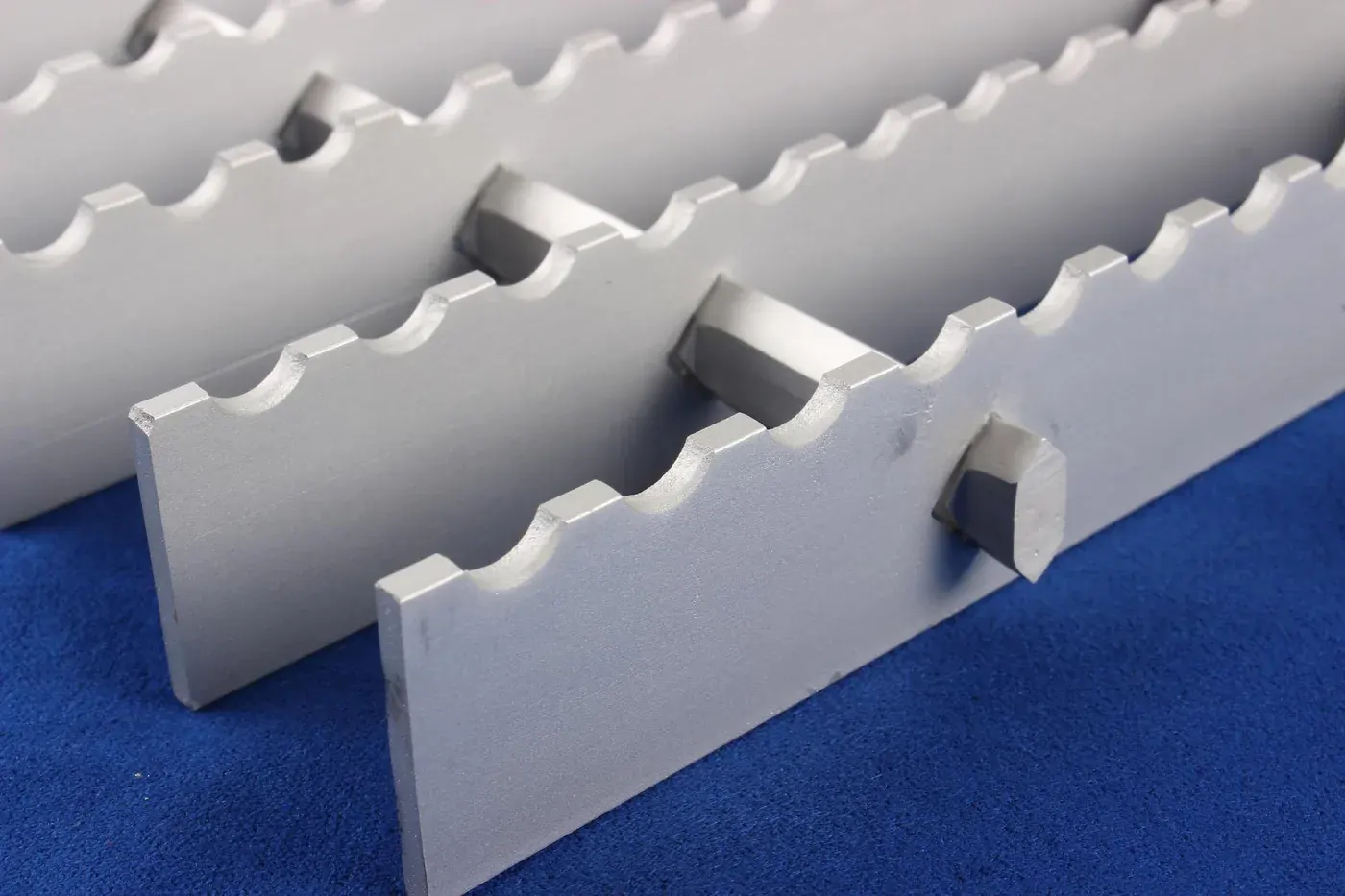
A toothed surface considered where additional slip resistance is required; profile availability is confirmed with the selected series.
Applications
These are typical application categories, not installation records for the panels pictured on this page. Confirm the alloy, surface, support layout, clear span and load case before selecting a series.
Typical use category
Safe, drained, ventilated walkways for photovoltaic arrays, pipe racks, tank farms and roof access routes.
View applicationTypical use category
Open-grid flooring for chemical plants, equipment platforms and mezzanines — strength, drainage and ventilation in one panel.
View applicationFabrication & QC
Packaging
FAQ
We aim to reply within one business day during published business hours.